SRS-Product Specifications
The formal standards for a 19-inch rack are available from the following:Electronic Industries Alliance EIA-310-D, Cabinets, Racks, Panels, and Associated Equipment, dated September, 1992. (Latest Standard Now REV E 1996)
International Electrotechnical Commission Multiple documents in available in French and English versions.
IEC 60297 Mechanical structures for electronic equipment - Dimensions of mechanical structures of the 482,6 mm (19 in) series
IEC 60297-1 Replaced by IEC 60297-3-100
IEC 60297-2 Replaced by IEC 60297-3-100
IEC 60297-3-100 Part 3-100: Basic dimensions of front panels, subracks, chassis, racks and cabinets
IEC 60297-3-101 Part 3-101: Subracks and associated plug-in units
IEC 60297-3-102 Part 3-102: Injector/extractor handle
IEC 60297-3-102 Part 3-103: Keying and alignment pin
IEC 60297-3-104 Part 3-104: Connector dependent interface dimensions of subracks and plug-in units
IEC 60297-3-105 Part 3-105: Dimensions and design aspects for 1U chassis
IEC 60297-4 Replaced by IEC 60297-3-102
IEC 60297-5 Multiple documents, -100, 101, 102, ... 107, replaced by IEC 60297-3-101
Deutsches Institut für Normung DIN 41494 - Multiple documents in German but some documents are available in English.
DIN 41494 Equipment practices for electronic equipment; mechanical structures of the 482,6 mm (19 inch) series
DIN 41494-7 Dimensions of cabinets and suites of racks.
DIN 41494-8 Components on front panels; mounting conditions, dimensions
DIN IEC 60297-3-100 (see above in IEC section)
A rack's mounting fixture consists of two parallel metal strips (also referred to as "rails" or "panel mount") standing vertically. The strips are each 0.625 inches (15.9 mm) wide, and are separated by a gap of 17.75 inches (451 mm), giving an overall rack width of 19 inches (480 mm). The strips have holes in them at regular intervals, with both strips matching, so that each hole is part of a horizontal pair with a center-to-center distance of 18.3 inches (460 mm).
The holes in the strips are arranged vertically in repeating sets of three, with center-to-center separations of 0.5 inches (13 mm), 0.625 inches (15.9 mm), 0.625 inches (15.9 mm). The hole pattern thus repeats every 1.75 inches (44 mm). Racks are divided into regions, 1.75 inches in height, within which there are three complete hole pairs in a vertically symmetric pattern, the holes being centered 0.25 inches (6.4 mm), 0.875 inch (22.225 mm), and 1.5 inches (38 mm) from the top or bottom of the region. Such a region is commonly known as a "U", for "unit", and heights within racks are measured by this unit. Rack-mountable equipment is usually designed to occupy some integral number of U. For example, an oscilloscope might be 4U high, and rack-mountable computers are most often 2U or 1U high. Occasionally, one may see fractional U devices such as a 1.5U server, but these are much less common.
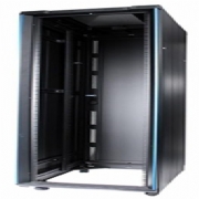
The height of a rack can vary from a few inches such as in a broadcast console to a floor mounted rack whose interior is 78.75 inches (2,000 mm) (45 rack units) high. Many wall mounted industrial equipment enclosures have 19" rack rails to support mounting of equipment.
IEC 60297-1 Replaced by IEC 60297-3-100
IEC 60297-2 Replaced by IEC 60297-3-100
IEC 60297-3-100 Part 3-100: Basic dimensions of front panels, subracks, chassis, racks and cabinets
IEC 60297-3-101 Part 3-101: Subracks and associated plug-in units
IEC 60297-3-102 Part 3-102: Injector/extractor handle
IEC 60297-3-102 Part 3-103: Keying and alignment pin
IEC 60297-3-104 Part 3-104: Connector dependent interface dimensions of subracks and plug-in units
IEC 60297-3-105 Part 3-105: Dimensions and design aspects for 1U chassis
IEC 60297-4 Replaced by IEC 60297-3-102
IEC 60297-5 Multiple documents, -100, 101, 102, ... 107, replaced by IEC 60297-3-101
Deutsches Institut für Normung DIN 41494 - Multiple documents in German but some documents are available in English.
DIN 41494 Equipment practices for electronic equipment; mechanical structures of the 482,6 mm (19 inch) series
DIN 41494-7 Dimensions of cabinets and suites of racks.
DIN 41494-8 Components on front panels; mounting conditions, dimensions
DIN IEC 60297-3-100 (see above in IEC section)
A rack's mounting fixture consists of two parallel metal strips (also referred to as "rails" or "panel mount") standing vertically. The strips are each 0.625 inches (15.9 mm) wide, and are separated by a gap of 17.75 inches (451 mm), giving an overall rack width of 19 inches (480 mm). The strips have holes in them at regular intervals, with both strips matching, so that each hole is part of a horizontal pair with a center-to-center distance of 18.3 inches (460 mm).
The holes in the strips are arranged vertically in repeating sets of three, with center-to-center separations of 0.5 inches (13 mm), 0.625 inches (15.9 mm), 0.625 inches (15.9 mm). The hole pattern thus repeats every 1.75 inches (44 mm). Racks are divided into regions, 1.75 inches in height, within which there are three complete hole pairs in a vertically symmetric pattern, the holes being centered 0.25 inches (6.4 mm), 0.875 inch (22.225 mm), and 1.5 inches (38 mm) from the top or bottom of the region. Such a region is commonly known as a "U", for "unit", and heights within racks are measured by this unit. Rack-mountable equipment is usually designed to occupy some integral number of U. For example, an oscilloscope might be 4U high, and rack-mountable computers are most often 2U or 1U high. Occasionally, one may see fractional U devices such as a 1.5U server, but these are much less common.
The height of a rack can vary from a few inches such as in a broadcast console to a floor mounted rack whose interior is 78.75 inches (2,000 mm) (45 rack units) high. Many wall mounted industrial equipment enclosures have 19" rack rails to support mounting of equipment.
Visit the SRS Products plc website for more information on SRS-Product Specifications
ENQUIRY FORM
More Products