
6DOF IMU 20 Click Board™
Product Code: MIKROE-5606
How Does The 6DOF IMU 20 Click Board™ Work? The 6DOF IMU 20 Click Board™ is based on the BMI323, a versatile 6DoF (six degrees of freedom) sensor module from Bosch Sensortec. This IMU combines precise acceleration and angular rate (gyroscopic) measurement with intelligent integrated features triggered by motion. It also has a 2K-byte FIFO that can lower the traffic on the selected serial bus interface by allowing the system processor to burst read sensor data. The BMI323 provides improved accelerometer performance as well as lower power consumption. In high-performance mode, using both the gyroscope and the accelerometer, the BMI323 shows a significant reduction in power consumption of nearly 15% compared to its predecessor, the BMI160. The BMI323 supports a wide range of use cases allowing customers to design it into various applications like angle and position detection, motion detection, tap recognition, and more. As mentioned, the BMI323 comprises a 16-bit triaxial gyroscope, a 16-bit triaxial accelerometer, and a 16-bit digital temperature sensor in a single package.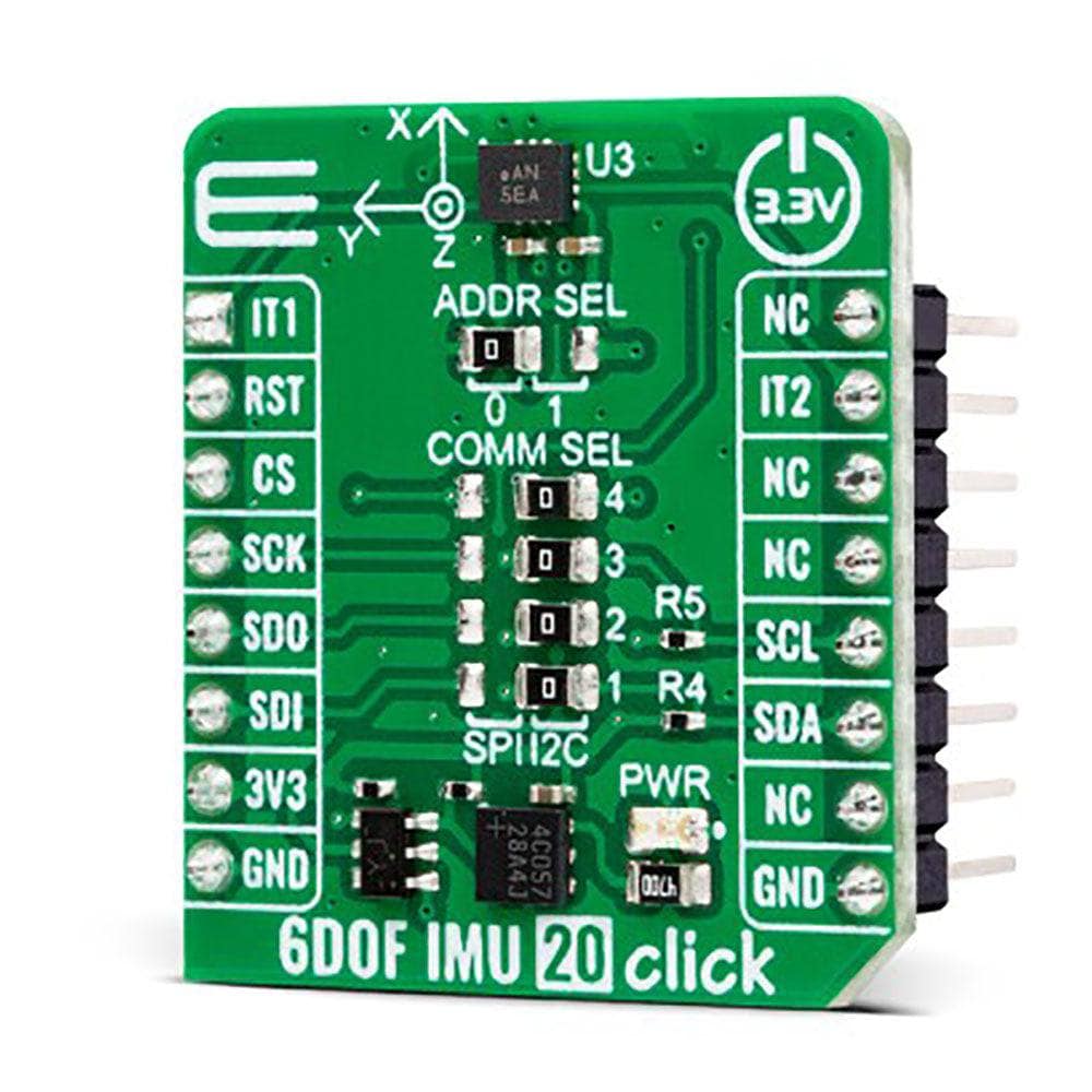
The accelerometer measures the direction and magnitude of the force applied to the sensor. In a free fall scenario, an accelerometer will report a vector of zeros. The gyroscope measures the rotational rate and reports vector zeros when the device rests. The gyroscope supports full-scale range settings from ±125dps to ±2000dps, and the accelerometer supports range settings from ±2g to ±16g. In addition, the BMI323 also includes an auxiliary temperature sensor.
This Click board™ allows using both I2C and SPI interfaces at a maximum frequency of 1MHz for I2C and 10MHz for SPI communication. Selection is made by positioning SMD jumpers marked COMM SEL to the appropriate position. All jumpers must be on the same side, or the Click board™ may become unresponsive. When the I2C interface is selected, the BMI323 allows the choice of its I2C slave address, using the ADDR SEL SMD jumper set to an appropriate position marked 1 or 0. In addition to communication pins, this board also possesses two interrupts, IT1 and IT2, routed to, where by default, the AN and INT pins stand on the mikroBUS™ socket, entirely programmed by the user through a serial interface. They signal MCU that a motion event has been sensed.
The 6DOF IMU 20 Click Board™ can only be operated with a 3.3V logic voltage level. The board must perform appropriate logic voltage level conversion before using MCUs with different logic levels. However, the Click board™ comes equipped with a library containing functions and an example code that can be used as a reference for further development.
SPECIFICATIONS
Type
Motion
Applications
It can be used for always-on applications like motion detection, step detector, plug 'n' play step counter, orientation and flat detection, single/double/triple tap detection, and more
On-board modules
BMI323 - versatile 6DoF sensor module from Bosch Sensortec
Key Features
Low power consumption, selectable interface, on-chip motion-triggered interrupt features, configurable accel/gyro range, 2KB on-chip FIFO, fast offset error compensation, high sensitivity and performance, and more
Interface
I2C,SPI
Compatibility
mikroBUS
Click board size
S (28.6 x 25.4 mm)
Input Voltage
3.3V
PINOUT DIAGRAM
This table shows how the pinout of the 6DOF IMU 20 Click Board™ corresponds to the pinout on the mikroBUS™ socket (the latter shown in the two middle columns).
Notes
Pin
Pin
Notes
Interrupt 1
IT1
1
AN
PWM
16
NC
NC
2
RST
INT
15
INT 2
Interrupt 2
SPI Chip Select
CS
3
CS
RX
14
NC
SPI Clock
SCK
4
SCK
TX
13
NC
SPI Data OUT
SDO
5
MISO
SCL
12
SCL
I2C Clock
SPI Data IN
SDI
6
MOSI
SDA
11
SDA
I2C Data
Power Supply
3.3V
7
3.3V
5V
10
5V
Power Supply
Ground
GND
8
Visit the Debug Store website for more information on 6DOF IMU 20 Click Board™
ENQUIRY FORM


