
8800 Retro Click Board™
Product Code: MIKROE-4771
How Does The 8800 Retro Click Board™ Work? The 8800 Retro Click Board™ as its foundation uses the AS1115, a compact dot-matrix 8x8 LED driver from AMS-AG. It includes a 4-bit PWM for each segment and only one resistor for LED current adjustment (LED brightness). The AS1115 consists of an integrated BCD code-B/HEX decoder, multiplex scan circuitry, segment and display drivers, and 64-bit memory. Internal memory stores the shift register settings, eliminating the need for continuous device reprogramming. That's why this board is ideal for seven-segment or dot matrix user-interface displays and other white goods or personal electronic applications. The LED columns have common cathodes connected to the digit-drive lines, where each of the 64 LEDs can be addressed separately. On initial Power-Up, the AS1115 registers are reset to their default values, the display is blanked, and the device goes into Shutdown mode. At this time, all registers should be programmed for Normal operation. The AS1115 features a low Shutdown current of typically 200nA and an operational current of typically 350μA.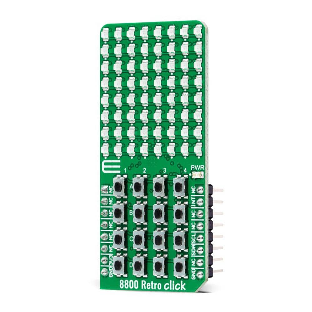
8800 Retro Click communicates with MCU using standard I2C 2-Wire interface, with a clock frequency up to 1MHz in the Fast Mode Plus. In addition, the AS1115 can read back 16 buttons and offers a detailed short/open LED error diagnostic. Therefore, to get a valid readback of buttons, it is recommended to read out the keyscan registers immediately after the IRQ interrupt pin, available on the INT pin of the mikroBUS™ socket, is triggered. In addition to the number-digits programming, this Click board™ can also be reset by software.
The 8800 Retro Click Board™ can be operated only with a 3.3V logic voltage level. The board must perform appropriate logic voltage level conversion before use with MCUs with different logic levels. However, the Click board™ comes equipped with a library containing functions and an example code that can be used, as a reference, for further development.
SPECIFICATIONS
Type
LED Matrix, Pushbutton/Switches
Applications
Can be used for seven-segment or dot matrix user-interface displays and other white goods or personal electronic applications
On-board modules
AS1115 - compact LED driver for 8x8 display screen programmed via a compatible 2-wire I2C interface from ASM-AG
Key Features
Low power consumption, individual LED segment control, readback for 16 buttons, interrupt feature, LED error detection, low power shutdown current, software reset, and more
Interface
I2C
Compatibility
mikroBUS
Click board size
L (57.15 x 25.4 mm)
Input Voltage
3.3V
PINOUT DIAGRAM
This table shows how the pinout on 8800 Retro Click corresponds to the pinout on the mikroBUS™ socket (the latter shown in the two middle columns).
Notes
Pin
Pin
Notes
NC
1
AN
PWM
16
NC
NC
2
RST
INT
15
INT
Interrupt
NC
3
CS
RX
14
NC
NC
4
SCK
TX
13
NC
NC
5
MISO
SCL
12
SCL
I2C Clock
NC
6
MOSI
SDA
11
SDA
I2C Data
Power Supply
3.3V
7
3.3V
5V
10
NC
Ground
GND
8
GND
GND
9
GND
Ground
ONBOARD SETTINGS AND INDICATORS
Label
Name
Default
Description
LD1
PWR
-
Power LED Indicator
LD2-LD65
-
-
8x8 LED Display
T1-T16
-
-
LED Addressing Buttons
8800 RETRO CLICK ELECTRICAL SPECIFICATIONS
Description
Min
Typ
Max
Unit
Supply Vo
Visit the Debug Store website for more information on 8800 Retro Click Board™
ENQUIRY FORM


