
BLE 5 Click Board™
Product Code: MIKROE-4120
How Does The BLE 5 Click Board™ Work? The BLE 5 Click Board™ based on the PAN1760A, a module from Panasonic that has some impressive features including the fact that it is Bluetooth 4.2 low energy support with ARM Cortex-M0 processor with Single Wire Debug (SWI) interface. The BLE 5 Click Board™ can either be operated in AT-Command or Host mode for very simple integration of Bluetooth connectivity into existing products, or in Stand-Alone mode. The BLE 5 Click Board™ in AT-Command or Host mode Click board™ Besides the commonly used UART RX, TX, RTS, and CTS, the BLE 5 Click Board™ has also WP0 and WP1 pins, which are routed to the PWM and AN pins of the mikroBUS™ socket, respectively. The PAN1760A modul contains internal antenna with receiver sensitivity -93 dBm, and the BLE 5 click board also features an SMA connector so it can be equipped with the appropriate 2.4 GHz antenna. The BLE 5 Click Board™ Stand-Alone mode, with 256 kB flash memory and 83 kB RAM for user application, the BLE 5 click can be used for many applications without the need for an external processor, saving cost, complexity, and space.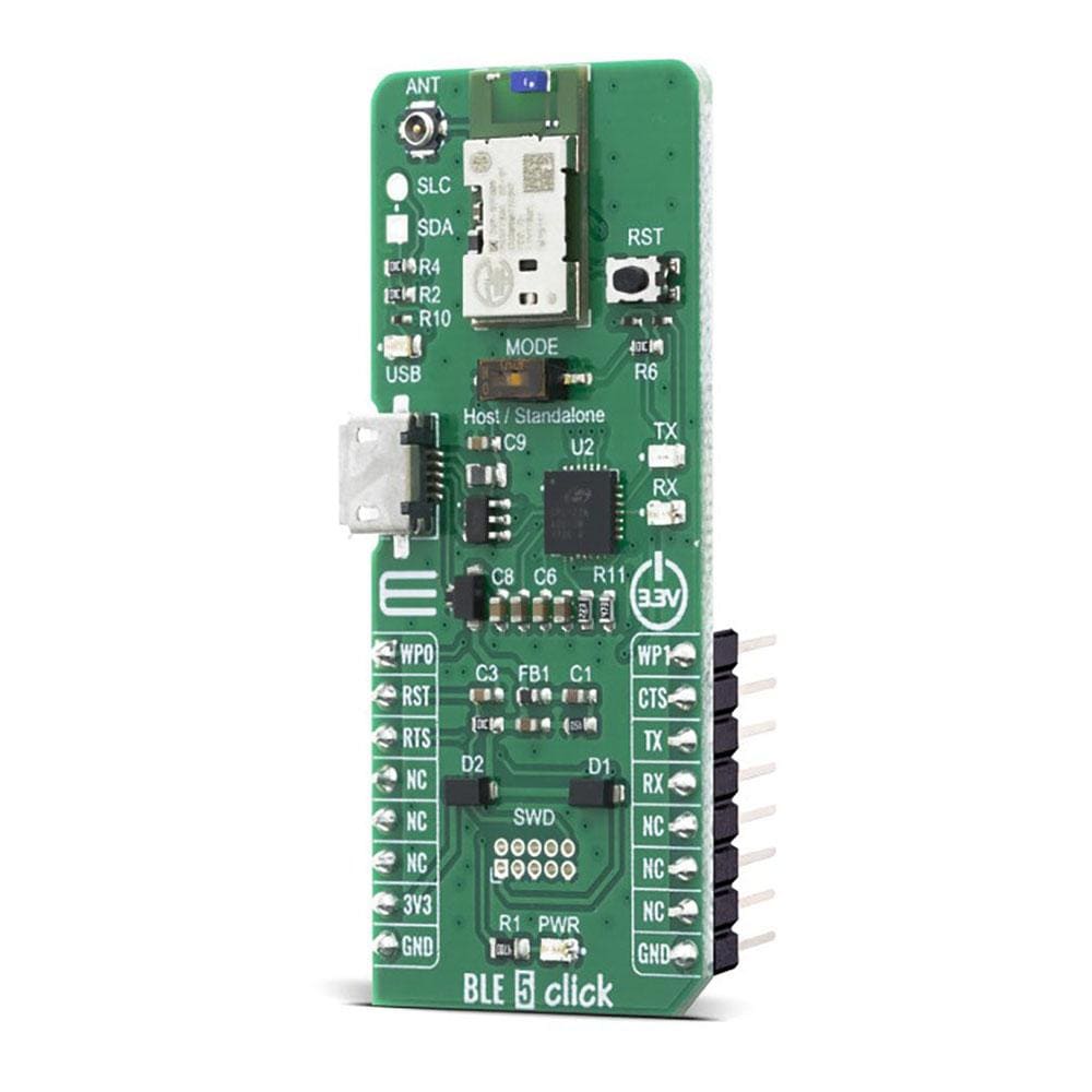
Peak power consumption of only 3.6 mA in Tx and Rx mode allows advanced wireless functionalities in IoT, medical, and industrial applications without compromising battery life.
The BLE 5 Click Board™ is equipped with the USB - micro B connector. It allows the module to be powered and configured by a personal computer. The CP2102N IC is a highly integrated USB to UART interface, from Silicon Labs. This IC adds USB to UART communication for embedded applications, registering itself as the virtual COM port, once the required drivers are installed. Besides the highly integrated USB to UART interface IC, this Click board™ is equipped with the additional ESD protection for the USB port, as well as the required signalization LEDs (RX, TX, power LED).
The BLE 5 Click Board™ is equipped with the I2C master header, the PAN1760A modul contain I2C bus master interface. The I2C interface can operate is 3.3V, cannot operate at different voltage from ones other interfaces are operate at. This pins can be used for connecting external I2C peripherals such as sensors to the module.
The BLE 5 Click Board™ is designed to be operated only with 3.3V logic level. A proper logic voltage level conversion should be performed before the Click board™ is used with MCUs with logic levels of 5V.
SPECIFICATIONS
Type
BT/BLE
Applications
Health, sports, and wellness devices as well as Industrial, home, and building automation; and smart phone, tablet, and PC accessories
On-board modules
PAN1760A , Bluetooth 4.2 low energy module from Panasonic
Key Features
Bluetooth 4.2 low energy compliant, integrated antenna, 83 kB RAM available for application
Interface
GPIO,UART,USB
Compatibility
mikroBUS
Click board size
L (57.15 x 25.4 mm)
Input Voltage
3.3V
PINOUT DIAGRAM
This table shows how the pinout on the BLE 5 Click Board™ corresponds to the pinout on the mikroBUS™ socket (the latter shown in the two middle columns).
Notes
Pin
Pin
Notes
Wake Up 0
WPO
1
AN
PWM
16
WP1
Wake Up 1
Reset
RST
2
RST
INT
15
CTS
UART clear to send
UART request to send
RTS
3
CS
RX
14
TX
UART Transmit
NC
4
SCK
TX
13
RX
UART Receive
NC
5
MISO
SCL
12
NC
NC
6
MOSI
SDA
11
NC
Power Supply
3.3V
7
3.3V
5V
10
NC
Ground
GND
8
GND
GND
9
GND
Ground
ONBOARD SETTINGS AND INDICATORS
Label
Name
Default
Description
LD1
PWR
-
Power LED Indicator
LD2
TX
-
TX LED Indicator
LD3
RX
Visit the Debug Store website for more information on BLE 5 Click Board™
ENQUIRY FORM


