
Bluetooth 2 Click Board™
Product Code: MIKROE-4087
How Does The Bluetooth 2 Click Board™ Work? The Bluetooth 2 Click Board™ uses the WT41u, a fully integrated Bluetooth 2.1 + EDR, class 1 module combining antenna, Bluetooth radio, and an on-board iWRAP Bluetooth Stack. The WT41u is a replacement for the WT41. The WT41u provides a superior 110 dB link budget and more than 1000-meter line-of-sight connectivity for Bluetooth applications where extreme radio performance or reliability is required. It also constitutes an ideal solution for developers that want to quickly integrate extremely high performing Bluetooth wireless technology into their design without investing several months in Bluetooth radio and stack development. The WT41u uses Bluegiga's iWRAP Bluetooth stack, which is an embedded Bluetooth stack implementing 13 different Bluetooth profiles and Apple iAP connectivity. By using WT41u combined with iWRAP Bluetooth stack and Bluegiga's excellent technical support, designers ensure quick time-to-market, and low development costs and risks.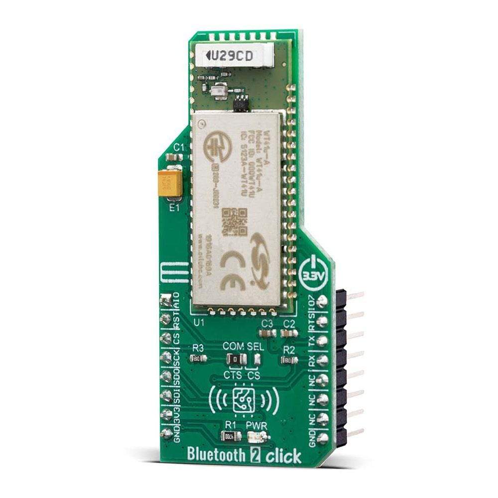
Targeted applications are Handheld terminals, Industrial devices, Point-of-Sale systems, PCs, Personal Digital Assistants (PDAs), Computer Accessories, Access Points, Automotive Diagnostics Units.
The Bluetooth 2 Click Board™ uses a standard UART interface for communicating with other serial devices. Implemented WT41u module UART interface provides a simple mechanism for communicating with other serial devices using the RS232 protocol. Four signals are used to implement the UART function. When WT41u is connected to another digital device, UART_RX and UART_TX transfer data between the two devices. The remaining two signals, UART_CTS and UART_RTS, can be used to implement RS232 hardware flow control where both are active low indicators. All UART connections are implemented using CMOS technology and have signaling levels of 0V and VDD. UART configuration parameters, such as data rate and packet format, are set using WT41u software.
Besides the commonly used UART RX, TX, RTS, and CTS, the Bluetooth 2 Click Board™ also has Reset, PIO7, and AIO pins, which are routed to the RST, PWM and AN pins of the mikroBUS™ socket, respectively. The SPI port can be used for system debugging. It can also be used for programming the Flash memory and setting the PSKEY configurations. WT41u uses 16-bit data and 16-bit address serial peripheral interface, where transactions may occur when the internal processor is running or is stopped. SPI interface is connected using the MOSI, MISO, CS, and SCK pins.
The communication interface can be selected by moving the SMD jumper designated as COM SEL to an appropriate position (CTS or CS) for RS232 or SPI protocol.
The Bluetooth 2 Click Board™ is designed to be operated only with a 3.3V logic level. A proper logic voltage level conversion should be performed before the Click board™ is used with MCUs with different logic levels.
SPECIFICATIONS
Type
BT/BLE
Applications
Handheld terminals, Industrial devices, Point-of-Sale systems, PCs, Personal Digital Assistants (PDAs), Computer Accessories, Access Points, Automotive Diagnostics Units.
On-board modules
The Bluetooth 2 Click Board™ uses the WT41u module, a fully integrated Bluetooth 2.1 + EDR class 1 module, from Silicon Labs.
Key Features
Exceptional radio performance (TX power: +20 dBm, RX sensitivity: -90 dBm). Superior radio performance 110dB link budget provides 1000+ meter line-of-sight connectivity.
Interface
GPIO,SPI,UART
Compatibility
mikroBUS
Click board size
L (57.15 x 25.4 mm)
Input Voltage
3.3V
Pinout Diagram
This table shows how the pinout of the Bluetooth 2 Click Board™ corresponds to the pinout on the mikroBUS™ socket (the latter shown in the two middle columns).
Notes
Pin
Pin
Notes
Analog
AIO
1
AN
PWM
16
IO7
GPIO
Reset
RST
2
RST
INT
15
RTS
UART RTS
Chip Select
CS
3
CS
RX
14
TX
UART TX
SPI Clock
SCK
4
SCK
TX
13
RX
UART RX
SPI Data OUT
SDO
5
MISO
SCL
12
NC
SPI Data IN
SDI
6
MOSI
SDA
Visit the Debug Store website for more information on Bluetooth 2 Click Board™
ENQUIRY FORM


