
Environment Click Board™
Product Code: MIKROE-2467
The Environment Click Board™ measures temperature, relative humidity, pressure and VOC (Volatile Organic compounds gases). The click carries the BME680 environmental sensor from Bosch. The Environment Click Board™ is designed to run on a 3.3V power supply. It communicates with the target microcontroller over SPI or I2C interface. You can use it to test your indoor air quality, to control HVAC (heating, ventilation, and air conditioning) systems, in a weather station, sports applications and more. BME680 Sensor Features The BME680 is as combined digital gas, humidity, pressure, and temperature sensor based on proven sensing principles. The humidity sensor provides an extremely fast response time for fast context awareness applications and high overall accuracy over a wide temperature range. The pressure sensor is an absolute barometric pressure sensor with extremely high accuracy and resolution. The integrated temperature sensor has been optimized for lowest noise and highest resolution.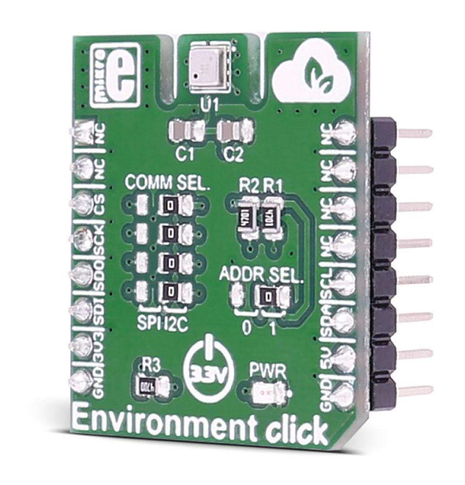
Its output is used for temperature compensation of the pressure and humidity sensors and can also be used for estimation of the ambient temperature.
The gas sensor within the BME680 can detect a broad range of gases to measure indoor air quality for personal well being. Gases that can be detected by the BME680 include Volatile Organic Compounds (VOC) from paints (such as formaldehyde), lacquers, paint strippers, cleaning supplies, furnishings, office equipment, glues, adhesives, and alcohol.
SPECIFICATIONS
Type
Environmental
Applications
Indoor air quality measurement, personalized weather station, home automation control, measuring ambient temperature, etc.
On-board modules
BME680 integrated environmental sensor
Key Features
A digital 4-in-1 sensor with gas, humidity, pressure and temperature measurement
Interface
I2C,SPI
Compatibility
mikroBUS
Click board size
S (28.6 x 25.4 mm)
Input Voltage
3.3V
PINOUT DIAGRAM
This table shows how the pinout on the Environment Click Board™ corresponds to the pinout on the mikroBUS™ socket (the latter shown in the two middle columns).
Notes
Pin
Pin
Notes
NC
1
AN
PWM
16
NC
NC
2
RST
INT
15
NC
Chip select
CS
3
CS
TX
14
NC
SPI clock
SCK
4
SCK
RX
13
NC
Master in slave out
MISO
5
MISO
SCL
12
SCL
I2C clock
Master out slave in
MOSI
6
MOSI
SDA
11
SDA
I2C data
Power supply
+3.3V
7
3.3V
5V
10
NC
Ground
GND
8
GND
GND
9
GND
Ground
JUMPERS AND SETTINGS
Designator
Name
Default Position
Default Option
Description
JP1
COMM. SEL.
Right
I2C
Selecting communication with MCU between SPI and I2C
JP2
ADDR. SEL.
Right
1
I2C address selection
JP3
COMM. SEL.
Right
I2C
Selecting communication with MCU between SPI and I2C
JP4
COMM. SEL.
Right
I2C
Selecting communication with MCU between SPI and I2C
JP5
COMM. SEL.
Right
I2C
Selecting communication with MCU between SPI and I2C
Visit the Debug Store website for more information on Environment Click Board™
ENQUIRY FORM


