
MCP73213 Click Board™
Product Code: MIKROE-2575
The MCP73213 Click Board™ carries the MCP73213 dual-cell Li-Ion/Li-Polymer battery charge management controller with input overvoltage protection from Microchip. The click is designed to run on either 3.3V or 5V power supply. It communicates with the target microcontroller over SPI. Note: The MCP73213 Click Board™ is designed to charge a dual-cell Li-Ion/Li-Polymer battery. The input voltage needs to be higher that the voltage of a dual-cell Li-Ion/Li-Polymer battery. MCP73213 CONTROLLER FEATURES The MCP73213 is a highly integrated Li-Ion battery charge management controller. The MCP73213 provides specific charge algorithms for dual-cell Li-Ion/Li-Polymer batteries to achieve optimal capacity and safety in the shortest charging time possible. The absolute maximum voltage, up to 18V, allows the use of MCP73213 in harsh environments, such as low-cost wall wart or voltage spikes from plug/unplug. An internal overvoltage protection (OVP) circuit monitors the input voltage and keeps the charger in shutdown mode when the input supply rises above the typical 13V OVP threshold.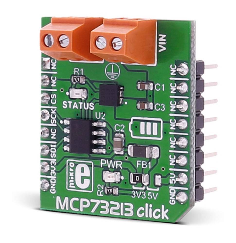
The OVP hysteresis is approximately 150 mV for the MCP73213 device.
How Does The MCP73213 Click Board™ Work?
First you need to connect the input voltage to the input screw terminal. Then to set the input voltage, because it needs to be larger than voltage of two series connected batteries for regular charging, (which means it needs to be >8V). We can change the charging current trough SPI interface.
Now just leave the batteries to charge, and when they are charged it will be signalized on the status LED.
SPECIFICATIONS
Type
Battery charger
Applications
Portable Media players, digital camcorders, handheld devices, etc.
On-board modules
MCP73213 dual-cell Li-Ion/Li-Polymer battery charge management controller
Key Features
13V Input Overvoltage Protection, Resistor Programmable Fast Charge Current: 130 mA-1100 mA, Elapse Safety Timer: 4 hr, 6 hr, 8 hr or Disable
Interface
SPI
Compatibility
mikroBUS
Click board size
S (28.6 x 25.4 mm)
Input Voltage
3.3V or 5V
PINOUT DIAGRAM
This table shows how the pinout of the MCP73213 Click Board™ corresponds to the pinout on the mikroBUS™ socket (the latter shown in the two middle columns).
Notes
Pin
Pin
Notes
NC
1
AN
PWM
16
NC
NC
2
RST
INT
15
NC
Chip Select
SPI_CS
3
CS
TX
14
NC
SPI Clock
SPI_SCK
4
SCK
RX
13
NC
NC
5
MISO
SCL
12
NC
SPI Master output slave input
SPI_MOSI
6
MOSI
SDA
11
NC
Power supply
+3.3V
7
3.3V
5V
10
+5V
Power supply
Ground
GND
8
GND
GND
9
GND
Ground
MAXIMUM RATINGS
Description
Min
Typ
Max
Unit
Input Voltage Range
4
16
V
Operating Supply Voltage
4.2
13
V
Fast Change Current Regulation
130
1100
A
Visit the Debug Store website for more information on MCP73213 Click Board™
ENQUIRY FORM


