
Relay 4 Click Board™
Product Code: MIKROE-5539
How Does The Relay 4 Click Board™ Work? The Relay 4 Click Board™ is based on dual J1031C3VDC, high-current single-pole double-throw (SPDT) signal relays from CIT Relay and Switch. The J1031C3VDC relay is well known for its reliability and durability, high sensitivity, and low coil power consumption housed in a small package with PC pin mounting. Despite its size (12.5x7.5x10 millimetre (LxWxH)), the J1031C3VDC relay can withstand up to 2A and 125VAC/60VDC maximum. These relays are designed to easily activate their coils by relatively low currents and voltages, making them a perfect choice that any MCU can control. As mentioned, the contact configuration of the J1031C3VDC is a single-pole double-throw (SPDT), which means that it has one pole and two throws. Based on the default position of the pole, one throw is considered normally open (NO) while the other is normally closed (NC), which is, in this case, its default position. When the coil is energized, it will attract the internal switching elements similar to a switch.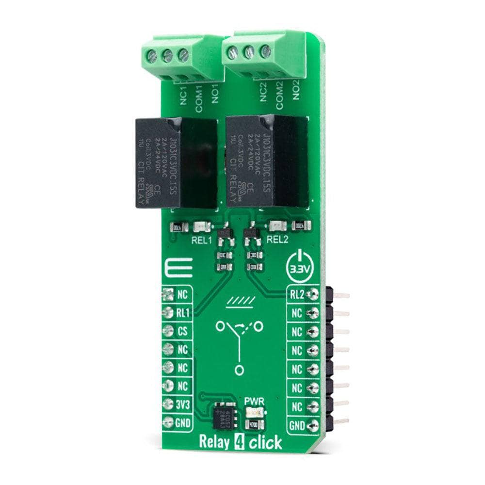
The Relay 4 Click Board™ uses two mikroBUS™ pins for its proper operation, the RL1 and RL2 pins routed to the RST and PWM pins of the mikroBUS™ socket. These pins control small N-channel MOSFET RET (Resistor Equipped Transistor) transistors that provide enough current for the relay coil. Two resistors are already integrated into the RET, providing it with the correct biasing and simplifying the design. Also, each relay has its own yellow LED indicator, which signalizes the state of the relay. When the current flows through the RET, the coil will be energized, and the relay will be switched from a closed to an open switch state.
The Relay 4 Click Board™ can be operated only with a 3.3V logic voltage level. The board must perform appropriate logic voltage level conversion before using MCUs with different logic levels. However, the Click board™ comes equipped with a library containing functions and an example code that can be used as a reference for further development.
SPECIFICATIONS
Type
Relay
Applications
Can be used for controlling high-power applications
On-board modules
J1031C3VDC - general-purpose signal relay from CIT Relay and Switch
Key Features
Low power consumption, reliable switching, high current, hig sensitivity, PC board mounting, SPDT configuration, relay activity indicators, and more
Interface
GPIO
Compatibility
mikroBUS
Click board size
L (57.15 x 25.4 mm)
Input Voltage
3.3V
PINOUT DIAGRAM
This table shows how the pinout of the Relay 4 Click Board™ corresponds to the pinout on the mikroBUS™ socket (the latter shown in the two middle columns).
Notes
Pin
Pin
Notes
NC
1
AN
PWM
16
RL2
Relay 2 Control
Relay 1 Control
RL1
2
RST
INT
15
NC
NC
3
CS
RX
14
NC
NC
4
SCK
TX
13
NC
NC
5
MISO
SCL
12
NC
NC
6
MOSI
SDA
11
NC
Power Supply
3.3V
7
3.3V
5V
10
NC
Ground
GND
8
GND
GND
9
GND
Ground
ONBOARD SETTINGS AND INDICATORS
Label
Name
Default
Description
LD1
PWR
-
Power LED Indicator
LD2-LD3
REL1-REL2
-
Relay Activity Status LED Indicators
RELAY 4 CLICK ELECTRICAL SPECIFICATIONS
Description
Min
Typ
Max
Unit
Supply Voltage
-
3.3
-
V
Current Rating
-
-
2
A
Switching Voltage
-
-
60
VDC
Visit the Debug Store website for more information on Relay 4 Click Board™
ENQUIRY FORM


