
RTC 21 Click Board™
Product Code: MIKROE-5541
How Does The RTC 21 Click Board™ Work? The RTC 21 Click Board™ is based on the PT7C4311, an ultra-low power, real-time clock (RTC) time-keeping device from Diodes Incorporated. The PT7C4311 is configured to transmit calendar and time data to the MCU (24-hour format) based on a 32.768kHz quartz crystal and comes with 56 bytes of general-purpose RAM. It reads and writes clock/calendar data from and to the MCU in units ranging from seconds to the last two digits of the calendar year, providing seconds, minutes, hours, dates, days, months, year, and century information. The end-of-the-month date is automatically adjusted for months with fewer than 31 days, including corrections for the leap year until 2100. The RTC 21 Click Board™ communicates with MCU using the standard I2C 2-Wire interface to read data and configure settings, supporting a Fast Mode operation up to 400kHz. It also incorporates one open-drain output labelled as FT, which can be used as a frequency test signal (512Hz square-wave password for frequency test purposes) or as a register-configurable output DC level when square-wave is disabled.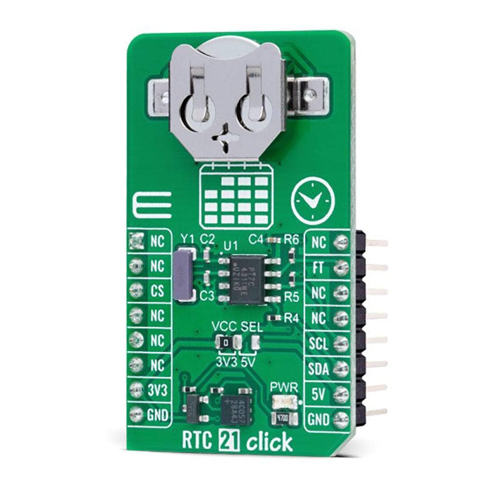
The PT7C4311 also includes an automatic backup switchover circuit allowing it to be used with a single-button cell battery for an extended period.
The RTC 21 Click Board™ can operate with either 3.3V or 5V logic voltage levels selected via the VCC SEL jumper. This way, both 3.3V and 5V capable MCUs can use the communication lines properly. However, the Click board™ comes equipped with a library containing easy-to-use functions and an example code that can be used, as a reference, for further development.
SPECIFICATIONS
Type
RTC
Applications
Can be used for various time-keeping applications, including daily alarms, metering applications, and others requiring an accurate RTC for their operation
On-board modules
PT7C4311 - real-time clock (RTC) from Diodes Incorporated
Key Features
Low power consumption, programmable square-wave output, high-speed I2C interface, clock/calendar counter, 24-hour format, 56 bytes RAM, automatic lepa year compensation, automatic backup switchover, and more
Interface
I2C
Compatibility
mikroBUS
Click board size
M (42.9 x 25.4 mm)
Input Voltage
3.3V or 5V
PINOUT DIAGRAM
This table shows how the pinout of the RTC 21 Click Board™ corresponds to the pinout on the mikroBUS™ socket (the latter shown in the two middle columns).
Notes
Pin
Pin
Notes
NC
1
AN
PWM
16
NC
NC
2
RST
INT
15
FT
Frequency Test/DC Level
NC
3
CS
RX
14
NC
NC
4
SCK
TX
13
NC
NC
5
MISO
SCL
12
SCL
I2C Clock
NC
6
MOSI
SDA
11
SDA
I2C Data
Power Supply
3.3V
7
3.3V
5V
10
5V
Power Supply
Ground
GND
8
GND
GND
9
GND
Ground
ONBOARD SETTINGS AND INDICATORS
Label
Name
Default
Description
LD1
PWR
-
Power LED Indicator
JP1
VCC SEL
Left
Logic Level Voltage Selection 3V3/5V: Left position 3V3, Right position 5V
RTC 21 CLICK ELECTRICAL SPECIFICATIONS
Description
Min
Typ
Max
Unit
Supply Voltage
3.3
-
5
V
Memory Size
-
-
56
bytes
Date Format
YY-MM-DD
Time Format
HH:MM:SS (24 hr)
Visit the Debug Store website for more information on RTC 21 Click Board™
ENQUIRY FORM


