
Smart Sens 2 Click Board™
Product Code: MIKROE-5207
How Does The Smart Sens 2 Click Board™ Work? The Smart Sens 2 Click Board™ is based on the BHI260AP, BME688, BMP390, and BMM150, a low-power programmable smart sensor, environmental and pressure sensor, and a magnetometer from Bosch Sensortec. The BHI260AP is based on the 32-bit microcontroller (Fuser2), mainly intended as a co-processor offloading the main CPU from any sensor data processing-related tasks, in this case, data from several onboard sensors. It integrates the Inertial Measurement Unit (6DoF IMU) and Event-Driven Software Framework, making the BHI260AP a complete sensor subsystem and computing platform for always-on sensor data processing algorithms at the lowest power consumption. The BMM150 is a geomagnetic sensor that allows measurements of the magnetic field in three perpendicular axes. An application-specific circuit (ASIC) converts the output of the geomagnetic sensor to digital results, which are then sent to the BHI260AP for signal processing over an auxiliary digital I2C interface.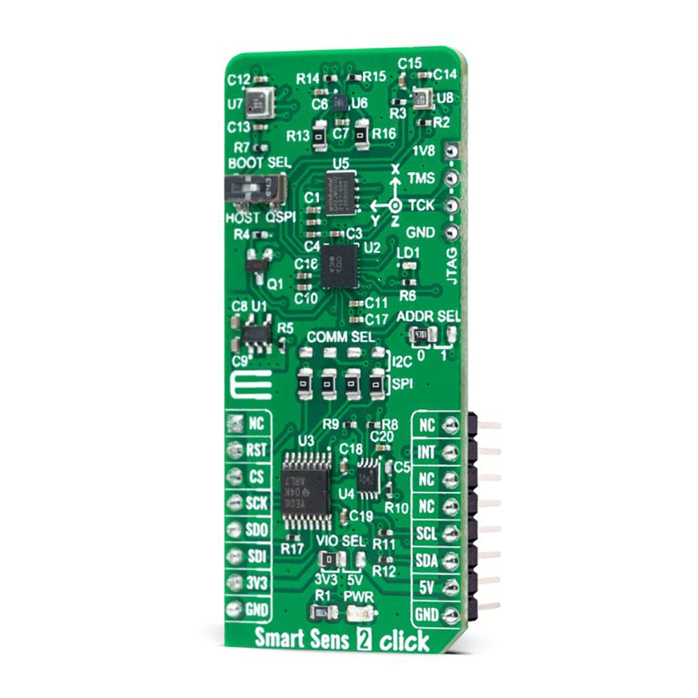
In the same way, both BME688 and BMP390 send their data for further processing via the I2C interface to the BHI260AP. The BME688 detects volatile organic (VOCs), sulfur compounds (VSCs), and other gases such as carbon monoxide and hydrogen in the ppb range, while the BMP390 performs pressure and temperature measurements.
The Smart Sens 2 Click Board™ allows using both I2C and SPI interfaces to communicate with the MCU. The selection can be made by positioning SMD jumpers labelled as COMM SEL in an appropriate position. Note that all the jumpers' positions must be on the same side, or the Click board™ may become unresponsive. While the I2C interface is selected, the BHI260AP allows choosing the least significant bit (LSB) of its I2C slave address using the SMD jumper labelled ADDR SEL. In addition to interface pins, this Click board™ also uses a Reset pin, RST pin on the mikroBUS™ socket, and INT pin of the mikroBUS™ socket, which indicates the data transfer request from the BHI260AP to the MCU alongside a red LED for event interrupt indication.
Since all onboard sensors for operation require a 1.8V voltage to work accurately, a small regulating LDO is used, the AP2112, providing a 1.8V out of mikroBUS™ power rails. That's why voltage-level translators are also featured, the TXB0106 and PCA9306. The interface bus lines are routed to the dual bidirectional voltage-level translators, allowing this Click board™ to work with both 3.3V and 5V MCUs properly.
In addition, an onboard BOOT switch is used to select whether the host interface shall be used (HOST position) or whether the BHI260AP shall attempt to boot from an onboard QSPI Flash memory, the W25Q32JW, and run in a Standalone operation mode (QSPI position). Besides, on the right side of this Click board™, an additional unpopulated header marked as JTAG is reserved for debugging purposes available through the JTAG interface pins (TCK and TMS).
The Smart Sens 2 Click Board™ can operate with both 3.3V and 5V logic voltage levels selected via the VIO SEL jumper. This way, it is allowed for both 3.3V and 5V capable MCUs to use the communication lines properly. However, the Click board™ comes equipped with a library containing easy-to-use functions and an example code that can be used, as a reference, for further development.
SPECIFICATIONS
Type
Environmental,Motion
Applications
Can be used for always-on sensor data processing algorithms at the lowest power consumption
On-board modules
BHI260AP - Programmable smart sensor from Bosch Sensortec BME688 - Environmental sensor from Bosch Sensortec BMP390 - Pressure sensor from Bosch Sensortec BMM150 - Magnetometer from Bosch Sensortec
Key Features
Smart sensor hub with integrated IMU sensor, onboard magnetometer, environmental and pressure sensor, boot mode selection, selectable communication, event interrupt indication, JTAG debugging, and more
Interface
I2C,SPI
Compatibility
mikroBUS
Click board size
L (57.15 x 25.4 mm)
Input Voltage
3.3V or 5V
PINOUT DIAGRAM
This table shows how the pinout of the Smart Sens 2 Click Board™ corresponds to the pinout on the mikroBUS™ socket (the latter shown in the two middle columns).
Notes
Pin
Pin
Notes
NC
1
AN
PWM
16
NC
Reset
RST
2
RST
INT
15
INT
Interrupt
SPI Chip Select
CS
3
CS
Visit the Debug Store website for more information on Smart Sens 2 Click Board™
ENQUIRY FORM


