
SolidSwitch 3 Click Board™
Product Code: MIKROE-5079
How Does The SolidSwitch 3 Click Board™ Work? The SolidSwitch 3 Click Board™ is based on the BD8LB600FS-C, an automotive eight-channel low-side load switch from Rohm Semiconductor. Every switch is controlled through a serial peripheral interface and includes an N-channel MOSFET that supports a maximum current of 1A. The BD8LB600FS-C offers flexible protection boundaries for systems against input voltage up to 5V and limits the output load current making this device ideal for driving resistive, inductive, and capacitive loads. The SolidSwitch 3 Click Board™ communicates with MCU through a standard SPI interface and operates at clock rates up to 5MHz, providing data in digital format of 16-bits. It also uses the Reset feature labelled as RST and routed to the RST pin of the mikroBUS™ socket. In addition to these pins, there are a few more like DIR and two input pins, IN1 and IN2 pins, routed to the AN, PWM, and INT pins of the mikroBUS™ socket. The DIR signal represents a transition to a direct mode activated by setting this pin to a high logic level.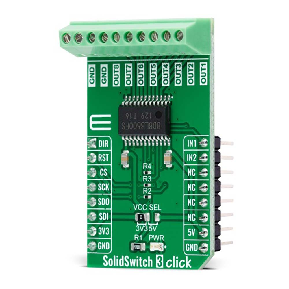
Depending on the set logic state on the DIR pin, pins IN1 and IN2 can be used to control the given output channels; IN1 represents the control of channels 1 and 5 when the DIR is at a low logic state, while IN2 defines the management of channels 2 and 6 when the DIR is at a low logic state. When the DIR is set to high logic state, then IN1 represents control of only channel 5 and IN2 only of channel 6.
As mentioned before, the BD8LB600FS-C also has built-in protection circuits, namely the overcurrent, the thermal shutdown, the open-load detection, and the voltage lock-out circuits. Moreover, this device also possesses a diagnostic output function during abnormal detection.
The SolidSwitch 3 Click Board™ can operate with both 3.3V and 5V logic voltage levels selected via the VCC SEL jumper. This way, it is allowed for both 3.3V and 5V capable MCUs to use the communication lines properly. However, the Click board™ comes equipped with a library containing easy-to-use functions and an example code that can be used, as a reference, for further development.
SPECIFICATIONS
Type
Relay
Applications
Can be used for driving resistive, inductive, and capacitive loads
On-board modules
BD8LB600FS-C - automotive eight-channel low-side load switch from Rohm Semiconductor
Key Features
Eight channel load switch, 16-bit SPI interface for diagnostics and control, built-in protection features, 1A maximum output current, and more
Interface
SPI
Compatibility
mikroBUS
Click board size
M (42.9 x 25.4 mm)
Input Voltage
3.3V or 5V
PINOUT DIAGRAM
This table shows how the pinout of the SolidSwitch 3 Click Board™k corresponds to the pinout on the mikroBUS™ socket (the latter shown in the two middle columns).
Notes
Pin
Pin
Notes
Direct Mode
DIR
1
AN
PWM
16
IN1
1/5 Channel Control
Reset
RST
2
RST
INT
15
IN2
2/6 Channel Control
SPI Chip Select
CS
3
CS
RX
14
NC
SPI Clock
SCK
4
SCK
TX
13
NC
SPI Data OUT
SDO
5
MISO
SCL
12
NC
SPI Data IN
SDI
6
MOSI
SDA
11
NC
Power Supply
3.3V
7
3.3V
5V
10
5V
Power Supply
Ground
GND
8
GND
GND
9
GND
Ground
ONBOARD SETTINGS AND INDICATORS
Label
Name
Default
Description
LD1
PWR
-
Power LED Indicator
JP1
VCC SEL
Left
Logic Level Voltage Selection 3V3/5V: Left position 3V3, Right position 5V
SOLIDSWITCH 3 CLICK ELECTRICAL SPECIFICATIONS
Description
Min
Typ
Max
Unit
Supp
Visit the Debug Store website for more information on SolidSwitch 3 Click Board™
ENQUIRY FORM


